Circuit diagram of the boost converter Boost converter voltage breaks down when load is connected Boost converter and motor driver circuit help : r/arduino
EMERGING TECHNOLOGIES: BOOST CONVERTER USING ARDUINO - SIMULATION IN
Diy boost converter circuit » wiring diagram
What is boost converter? circuit diagram and working
Emerging technologies: boost converter using arduinoBoost converter circuit diagram using mosfet Analysis of four dc-dc converters in equilibriumSchematic diagram of a boost converter and its control circuit.
Circuit diagram of a boost converterBoost converter schematic diagram Arduino converter proteusBoost converter circuit diagram using arduino.

Boost converter dc diagram simple circuit topology converters analysis mode voltage conduction discontinuous output equilibrium four schematic engineering articles astable
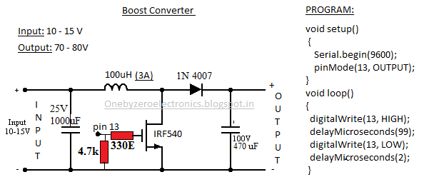
Boost converter: basics, working, design & applicationBoost converter arduino simple using irf540 mosfet make Solved shows a circuit diagram of a boost converterCircuit diagram of boost converter.
Arduino dc boost converter design circuit with control loop10+ boost converter circuit diagram Boost converter voltage simple high very arduino nuclearrambo pwm mosfet waveform generates drive which used wordpressPrzetwornica tranzystor pali voltage theorycircuit.
Working of this circuit
The boost converter circuit and its controlEngineering and information: simple boost converter using arduino Circuit diagram of boost converterVery simple high voltage converter.
Boost converter circuit 555Arduino dc boost converter design circuit with control loop Converter circuit diagram schematic 12vBoost converter circuit diagram [17].

Boost converter circuit using 555 timer ic
Boost converter circuit diagramSimulation diagram of boost converter circuit. Electronic – arduino boost converter. connecting load makes converterPin on its electronics.
Boost converter dc arduino circuit feedback lm2577 schematic diagram potentiometer electronoobs code circuitosBoost converters (step-up converter) Boost circuit regulator diagram waveform off theory operation modes switch capacitor duringFeedback boost converter arduino code.

What is boost converter? operating principle and waveform
Converter schematic .
.


.png)


